Project 4: Programmable Lights
The purpose of this project is to build a very simple programmable light display. We will define a machine model with a small instruction set and write a state machine to implement it.
Tasks
The programmable light display will be a simple state machine that can execute eight possible instructions and read a sequential program that is 16 instructions long. The state machine has one register, the light register [LR], which holds 8-bits. The eight possible instructions and their bit codes are as follows.
| Code | Meaning |
|---|---|
| 000 | Load "00000000" into the LR | 001 | shift the LR right by one position, fill from the left with a '0' |
| 010 | shift the LR left by one position, fill from the right with a '0' |
| 011 | add 1 to the LR |
| 100 | subtract 1 from the LR |
| 101 | invert all of the bits of the LR |
| 110 | rotate the LR right by one position (rightmost bit becomes leftmost bit) |
| 111 | rotate the LR left by one position (leftmost bit becomes rightmost bit) |
- Start by creating a project in Quartus. I'll refer to the project as lights for the top level entity.
-
Create a simple read-only memory [ROM] using VHDL. Create a VHDL file
and drop in a simple template, such as the unsigned adder. Remove
the generic part of the entity statement and rename the entity as
lightrom in both the entity and architecture statements.
Save the file as lightrom.vhd and add it to the current project.
The lightrom should take one input signal addr that should be a 4-bit std_logic_vector. It should have one output signal data that should be a 3-bit std_logic_vector.
The content of your architecture should be a single conditional signal assignment. You can use the following for testing. Later, you will need to write your own program. The 3-bit values stored at each address location are the program.
data <= "000" when addr = "0000" else -- move 0s to LR 00000000 "101" when addr = "0001" else -- bit invert LR 11111111 "101" when addr = "0010" else -- bit invert LR 00000000 "101" when addr = "0011" else -- bit invert LR 11111111 "001" when addr = "0100" else -- shift LR right 01111111 "001" when addr = "0101" else -- shift LR right 00111111 "111" when addr = "0110" else -- rotate LR left 01111110 "111" when addr = "0111" else -- rotate LR left 11111100 "111" when addr = "1000" else -- rotate LR left 11111001 "111" when addr = "1001" else -- rotate LR left 11110011 "010" when addr = "1010" else -- shift LR left 11100110 "010" when addr = "1011" else -- shift LR left 11001100 "011" when addr = "1100" else -- add 1 to LR 11001101 "100" when addr = "1101" else -- sub 1 from LR 11001100 "101" when addr = "1110" else -- bit invert LR 00110011 "011"; -- add 1 to LR 00110100 -
Create a new VHDL file lights.vhd. Use the full design
template for the Moore state machine. Modify the entity and
architecture statements to use lights as the name of the circuit.
The entity port statement should have four signals. The inputs should be a clock and a reset, both type std_logic. The outputs should be a lights signal that is an 8 bit std_logic_vector and a signal called IRView that is a 3-bit std_logic_vector. If you wish, you can add an output signal called PCView that would be a 4-bit std_logic_vector.
The lights circuit needs four internal signals. These should be declared inside the architecture, before the begin statement. The signals are: IR, a 3-bit std_logic_vector; PC, a 4 bit unsigned; LR, an 8 bit unsigned; ROMvalue, a 3-bit std_logic_vector; and state which is of type state_type.
Our state machine will have only two states: sFetch and sExecute. The sFetch state should assign ROMvalue to the IR, add one to the PC and then set the state to sExecute. The sExecute state should use a case statement on the value of the IR and execute the proper action given the machine instruction table above.
The reset case should set the PC, IR and LR to all zeros and the state to sFetch.
Using concurrent signal assignments, assign the IR to the IRview output and assigne the LR to the lights output. When you assign the LR to the lights output you will need to cast it to a std_logic_vector, as below.
lights <= std_logic_vector(LR);
Fill out the sExecute part of the statement. This should be a case statement on the IR. Each case should consist of a single signal assignment statement to LR.
-
You need to connect your lightrom circuit to the lights circuit.
Right after the architecture statement, add the following template.
component lightrom
    <port statement>
end component;
Copy the port statement from your lightrom circuit and paste it into the component statement in place of <port statement>.
In the body of your architecture, make an instance of your lightrom using the port map statement. You can use the component instantiation template (VHDL->Constructs->Concurrent Statements->Instances) or look back at the lab page. Connect the addr input to the PC signal, cast as a std_logic_vector. Connect the data output to the ROMvalue signal.
-
Download the following lightsbench.vhd
test file and save it in your working directory. Then open a
terminal, cd to your working directory and run the following commands.
ghdl -a lightsbench.vhd lights.vhd lightrom.vhd
ghdl -e lightsbench
ghdl -r lightsbench --vcd=lightsbench.vcd
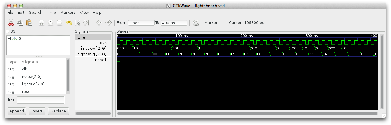
gtkwave lightsbench.vcdAfter inserting the signals and zooming the view to fit, you should get a result like the following.
-
Set up the pins so the light signal drives 8 of the green lights. Set
up the IRview signal so it lights up three of the red lights. Connect
the clock to the 24 MHz clock (pin A12) and the reset to the right
push button (pin R22).
Before testing your circuit on the board, you will need to slow down the circuit. Add the following process and assignment to your architecture.
  -- used to slow down the clock
  process(clk, reset)
    begin
      if reset = '0' then
        counter <= "0000000000000000000000000";
      elsif (rising_edge(clk)) then
        counter <= counter + 1;
      end if;
  end process;

  slowclock <= counter(24);
Add the following to your set of internal signal declarations.
  signal slowclock : std_logic;
  signal counter: unsigned (24 downto 0);
Then modify your main state process sensitivity list to slowclock instead of clk. (Your process was probably something like process(clk, reset). Change that to process(slowclock, reset). Also, change the rising_edge test from clk to slowclock. Now your state machine is running 32 million times slower than the clock. You can adjust the speed of your circuit by assigning different bits from the counter to the slowclock signal.
Now test your circuit on the board.
- Write two different programs of 16 instructions each by modifying the lightrom circuit. Be sure to save copies of your work in different files so you can demonstrate them later. Test out your programs and be prepared to demonstrate one of them before lab. Note that you can simulate your programs using the save lightsbench test file.
Extensions
- Make longer programs.
- Add instructions to the system. Make branch instructions, for example.
- Add a hold/free button to the display.
- Add a button that lets you speed up or slow down the display.
- Be creative.
Writeup
Create a wiki page with your writeup. For each task, write a short description of the task, in your own words.
- Include a description of your top-level design.
- Include the two programs you wrote using the simple instruction set.
- Include a picture, or preferably a video, of your circuit in simulation.
- Describe the hardware testing you undertook to prove the circuit works.
- Include a description, and pictures, of any extensions.
- Please supply a list of people you worked with, including TAs, and professors. Include in that list anyone whose code you may have seen, such as those of friends who have taken the course in a previous semester.
Handin
Give your wiki page the label cs232f16project4.
Put your VHDL files in a folder called project4 in your private subdirectory on Courses. Be sure your code is properly commented.