Lab 5: LED Controller |
Goals
- Design a circuit based on component specifications.
- Wire components based on self-drafted circuit design.
- Map the potentiometer ratings to color.
|
Part 1: Design Circuit |
Design Your Circuit
Draw a circuit diagram representing your RGB LED and potentiometer wired to the Arduino.
RGB LED - Common Cathode
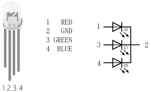
- Using the datasheet, figure out which pin is the common cathode.
- Calculate required resistance for each anode pin. Include calculations in your lab report. Use the LED's forward voltage and forward current from the datasheet.
- Equations:
- Vresistor = Iresistor * Rresistor
- Vpower = VLED + Vresistor
- Figure out which pins of the Arduino you can use analogWrite() with.
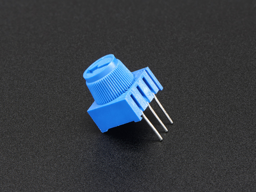
Potentiometer
- Connect VCC to the Arduino's 3.3V supply.
- Connect GND to the Arduino's ground. Use a different ground pin on the Arduino for the RGB LED and the potentiometer.
- Connect OUT to an analog input pin.
|
Part 2: Potentiometer |
Wire the Potentiometer
Wire your potentiometer to your circuit based on your circuit diagram.
Test the Potentiometer
Print the potentiometer values to Serial to make sure it's working.
|
Part 3: RGB LED |
Wire the RGB LED
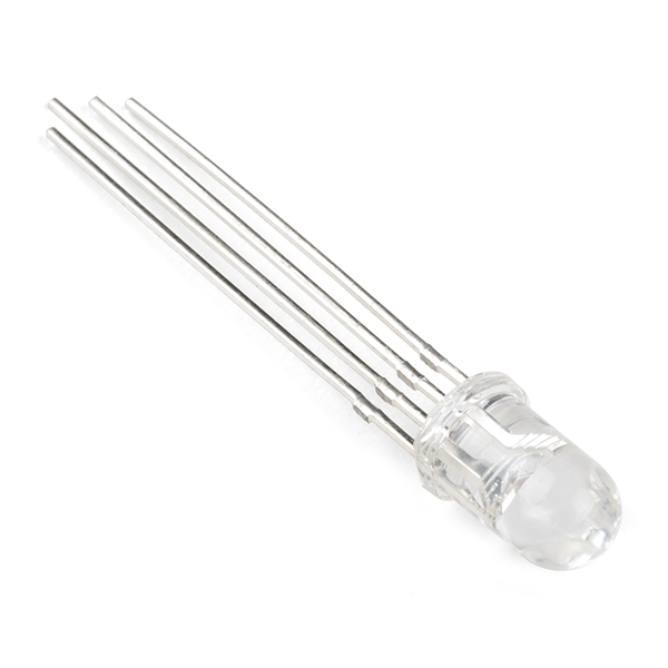
Wire your RGB LED to your circuit based on your circuit diagram.
Test the RGB LED
- Using registers (Port Registers & Pin Mapping) set the R, G and B pins to OUTPUT.
- Write 255 to each pin individually to confirm which is which.
Program the circuit
Modify the code so that the color LED of the smoothly changes between colors based on the value of the potentiometer. For example, smoothly transitioning between Blue, Green, Yellow, Red and Purple.
- 0 should be Blue. RGB = (0, 0, 255).
- 256 should be Green. RGB = (0, 255, 0).
- 512 should be Yellow. RGB = (255, 128, 0).
- 768 should be Red. RGB = (255, 0, 0).
- 1024 should be Purple. RGB = (128, 0, 128).
|
Check-in |
Check-in
The goal is for you to have the potentiometer and LED working by the check-in. You can only turn in extensions if your check-in is ontime and complete.
Submit a video and Check-in document on Google Classroom
Upload a 0.5-2 minute Documentation Video with narration.
- Show that that LED responds to different potentiometer levels, smoothly transitioning between colors.
- Describe what is happening.
Attach a Google Doc Check-in which includes:
- Documentation of the circuit:
- Resistance calculations for R, G and B.
- Drawing of the circuit you designed.
- Clear photo of the circuit in which the wiring is clearly visible, wired correctly.
- Video Description Paragraph:
- 2-5 sentences describing what is happening in the video.
- If complete: How does it work?
- If incomplete: What is the current issue? Where are you stuck?
- Project Idea:
- 2-5 sentences describing an idea for a project that incorporates the microphone with the piezo element, IR sensor and/or the vibrating motor. (Button, potentiometer, and red LED are optional).
- What is it?
- What materials would you need?
- How would you implement it?
|