Project 05 |
Goals
- Use registers to read from analog pin.
- Calculate the amplitude of a signal using peak to peak.
- Create a sound meter using a microphone and an LED.
|
Setup |
Setup
Start with your code from Lab 5.
Save it as a new Arduino project titled colbyUsername_P05 (with your colby username, mine would be hewolfe_P05).
|
Reading Analog Inputs from Registers |
Reading Analog Inputs from Registers
We will be using the ADC to convert signals from Analog Input 0.
The Atmel ATmega328P Analog to Digital Conversion Module by Dr. Ming Hsieh at USC, is a great resource, as well as the ATmega328P Datasheet. Specifically 7.3.1 for the global interrupt flag, and Section 24 (24.9.1 ADMUX register and 24.9.2 ADCSRA register).
Setting Registers
- Configure the REFS[1:0] bits to select AVCC as the high reference voltage.
- Configure the ADPS[2:0] bits to select the clock prescaler value as 128.
- Configure the MUX[3:0] bits to use A0.
- Set global interrupt flag on SREG.
- Set the ADIE bit in ADCSRA to a one. This enables the ADC interrupt.
- Set the ADEN bit in ADCSRA to a one. This enables the ADC.
- Set the ADSC bit in ADCSRA to a one. This starts the first conversion.
Setting up the interrupt
- Write an interrupt service routine (ISR) for the ADC_vect interrupt.
ISR(ADC_vect)
- In the ISR, read the result from ADC by setting a global volatile variable to ADC.
- Start another conversion by setting registers so that the ADSC and ADIE bits are 1.
Use A0's value
- In the loop, print the global volatile variable to Serial.
- In the loop, set the color of your RGB LED based on A0's value.
- Use a delay, so that your loop is running at a rate that you can easily read.
|
Microphone |
Circuit Diagram
Create a new circuit diagram with your microphone instead of the potentiometer.
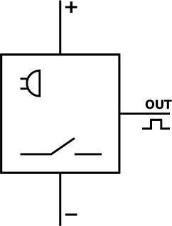
Microphone
- Connect VCC to the Arduino's 3.3V supply.
- Connect GND to the Arduino's ground. Use a different ground pin on the Arduino for the RGB LED and the microphone.
- Connect OUT to an analog input pin.
What are your readings from the microphone? I typically get readings between 300-350.
|
Create Volume Meter |
Peak to Peak
We want to find the minimum and maximum microphone readings over a window of 64 measurements. Ignore any spurious readings >= 1024 or <= 0. When the window is complete, calculate the peakToPeak (maximum-minimum), and reset the maximum, minimum and count.
Test the system, by printing peakToPeak in the loop to the serial port and see how it responds to different volume levels.
Recommendations
- Have a few volatile variables, to represent the count, minimum, maximum and peak2peak
- Conditionals & short calculations can be done in the interrupt, but other functions like analogWrite() or Serial.print() should not be in the interrupt.
Create Volume Meter
Have RGB LED respond to peak_to_peak value.
|
Analysis |
Test your code
Use your computer or cell phone to produce sounds at different volumes. Does the LED respond as expected?
|
Extension |
Extensions
Optionally you can complete 1-2 extensions. Extensions can build on the pre-existing circuit for this project or can be a new circuit. The complexity of the chosen extension, the implementation and the quality of the documentation effects the final grade. I encourage ideas not on the list. I reccommend discussing your extension idea with me (in person or over email) if you are unsure if it reasonable.
Extension code must be separate from the project.
Software Extension
Software extensions build on the pre-existing circuit for this project.
Here are some ideas:
- Use timers to control the PWM of the LED pins.
- Implement a lowpass or high pass filter, and see how that can be used to reduce noise from the signal.
- Implement FFT to detect the pitch of the incoming signal.
Hardware Extension
Design and implement an idea for a new project which involves adding new components and modifying the circuitry.
- It must incorporate the materials from this project; the microphone and RGB LED.
- It must include atleast one of the following components: a piezo element, bluetooth, accelerometer, the IR emitters, IR receivers, and/or the vibrating motors.
- It can include potentiometers, buttons and/or red LEDs.
Include in the documentation:
- A circuit diagram.
- A photograph of the circuit board.
Document your Extensions
- Submit your code on filer in a folder inside your project folder.
- A 1-3 minute video documenting your extension working.
- A description of the extension.
- A section on implementation.
- A section on results & reflection.
- Include any relevant photographs, drawings, charts or graphs.
|
Submission |
Submit your code on Filer
Submit your arduino code in a folder titled colbyUsername_P05.
Submit your report and video on Google Classroom
Upload a 1-3 min Documentation Video of your project working. Describe what is happening.
Attach a Google Doc Report which includes:
- Photo of circuit and updated circuit diagram. Clear photo of the circuit in which the wiring is clearly visible.
- Implementation Section
- Explain how you implemented the project.
- Explain what algorithms or techniques you used.
- Results & Reflection Section
- How well does your implementation work?
- What were the results of your tests?
- What were the results of your analysis?
- Acknowledgements Section
- What resources did you use? Include websites, books and anyone you received help from or discussed the project with.
|