CS 353 Fall 2020     Syllabus       Labs/Projects

Lab Goals Part 1: LED Part 2:
IR Emitter
Part 3:
IR Detector
Part 4:
IR Switch

Lab 1: Infrared Switch

Goals

  • Wire a circuit.
  • Calculate the required resistor for an IR Emitter.
  • Program a micro-controller.
  • Read from a sensor and write it to the Serial Port.
  • Build a switch that turns on an off an LED by blocking the path between an Infrared Emitter and Infrared Detector.

Part 1: LED

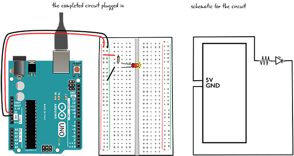
We will be building the LED circuit described in:
Ch 5. Electricity and Metering of Learn Electronics with Arduino


Italian Trulli

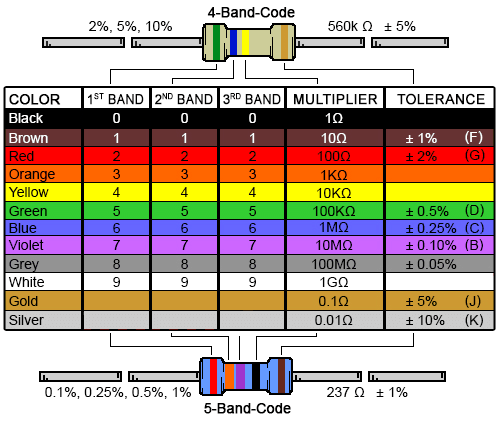
First, figure out which resistor is the 220-ohm resistor


Italian Trulli

Italian Trulli

Next, build the circuit


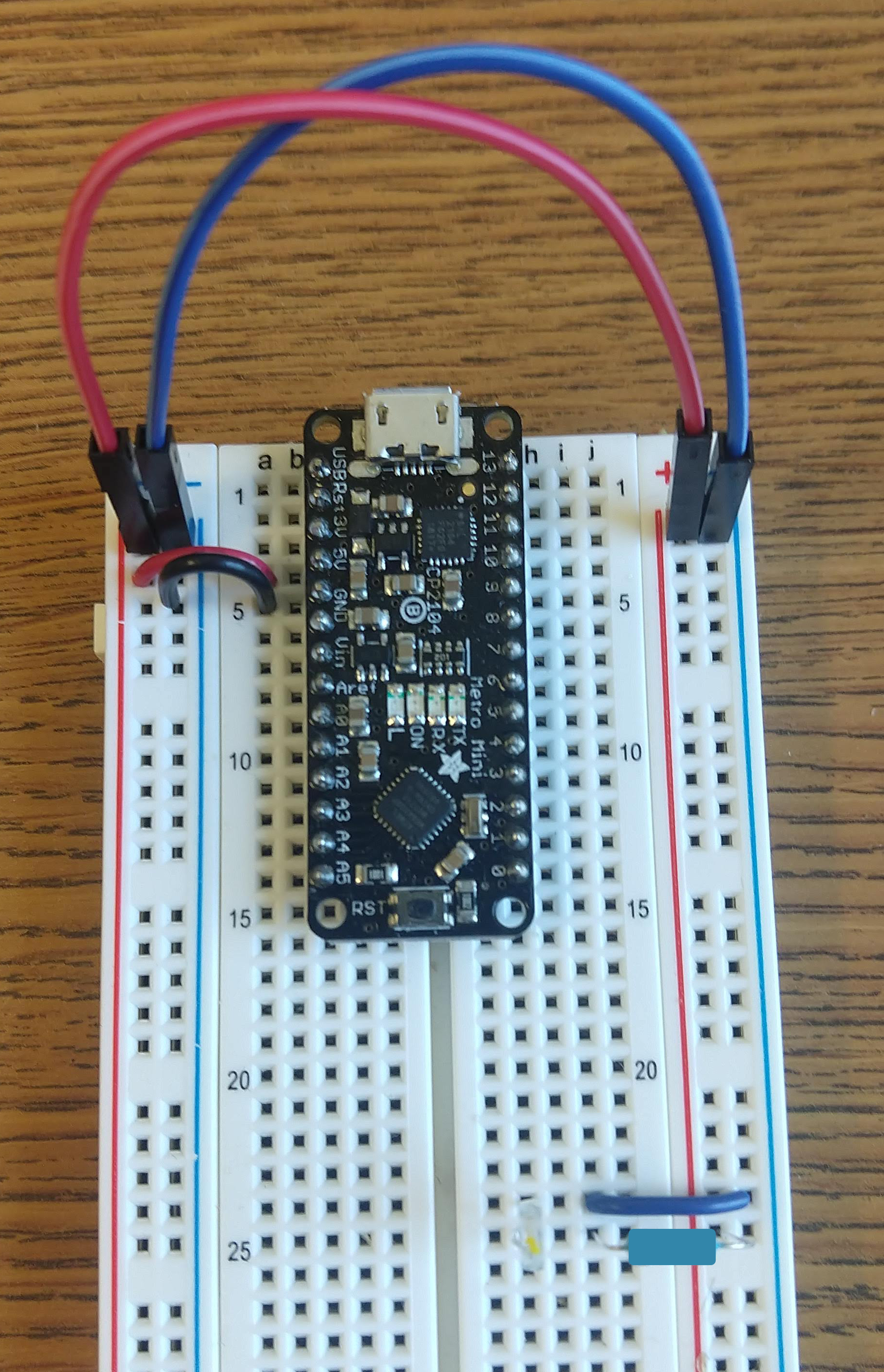
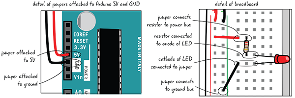
  1. Attach one end of a jumper to the 5V pin on the Arduino, and the other end of the jumper to the power bus on your breadboard (that’s the column marked with a red +).
  2. Grab another jumper and attach one end to the GND pin on the Arduino, and the other end to the ground bus on your breadboard (that’s the column marked with the green –).
  3. Connect a jumper from the power bus to a row of tie points.
  4. Connect one lead of a 220-ohm resistor to the same row of tie points. The other end goes in another row of tie points.
  5. Connect the anode (long leg) of the LED to the other lead of the resistor.
  6. Attach a jumper from the cathode (short leg) of the LED to the ground bus.


Italian Trulli

Part 2: Infrared Emitter

Italian Trulli

Build a circuit to power the Infrared Emitter

The infrared emitter is a light emitting diode (LED) that specifically emits near-infrared light (just below the visible spectrum). The component with the yellow dot on top is the IR Emitter.

  • Using Ohm's Law, calculate the resistor required for the infrared emitter.
  • Remember in a series circuit, the current that flows through each of the components is the same.
  • Use the IR Emitter datasheet to look up it's Continuous Forward Current and estimate the maximum Forward Voltage.
  • Replace the red LED with the IR Emitter, and the 220-ohm resistor with your newly calculated resistor.
Equations
  • Vresistor = Iresistor * Rresistor
  • Vpower = VIR emitter + Vresistor

Part 3: Infrared Detector

Build a circuit to read from an Infrared Detector

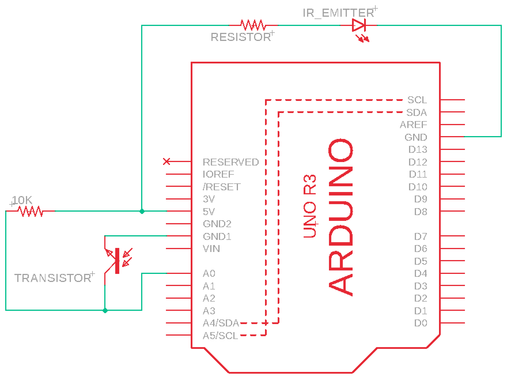
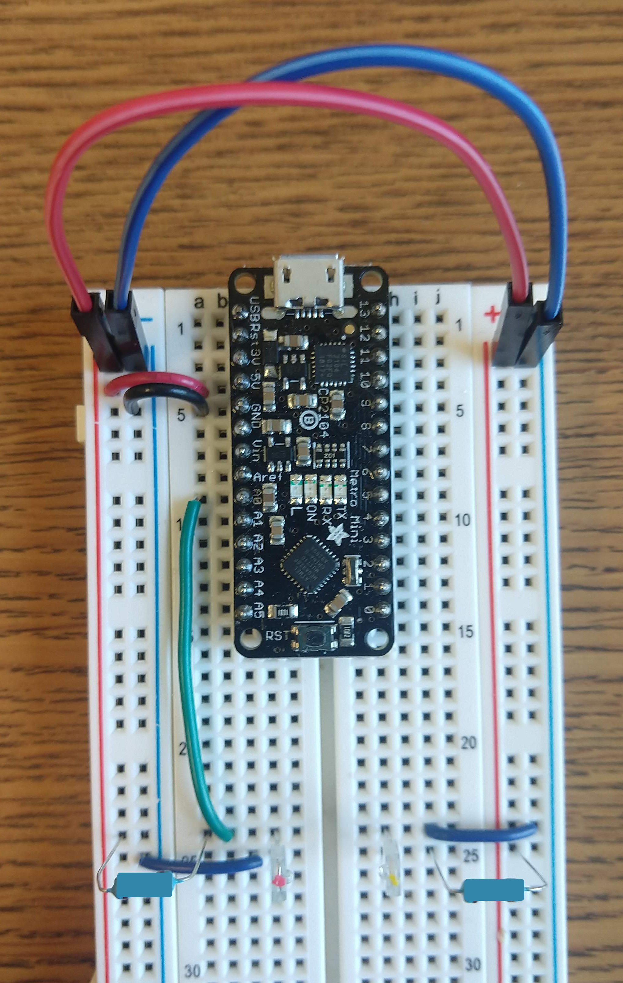
Given the infrared-sensitive phototransistor, build the circuit below.

A phototransistor is a sensor that is able to detect light levels and alter the current flowing between emitter and collector according to the level of light it receives.

The component with the red dot on top is the IR Detector. Use a 10k resistor for the IR Detector Circuit.

Italian Trulli Italian Trulli

Connect to the Metro Mini

  • Using a micro USB cable, plug your arduino into the computer.
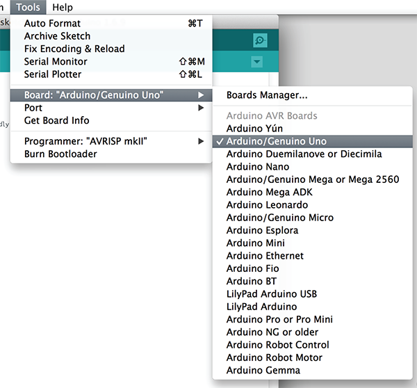
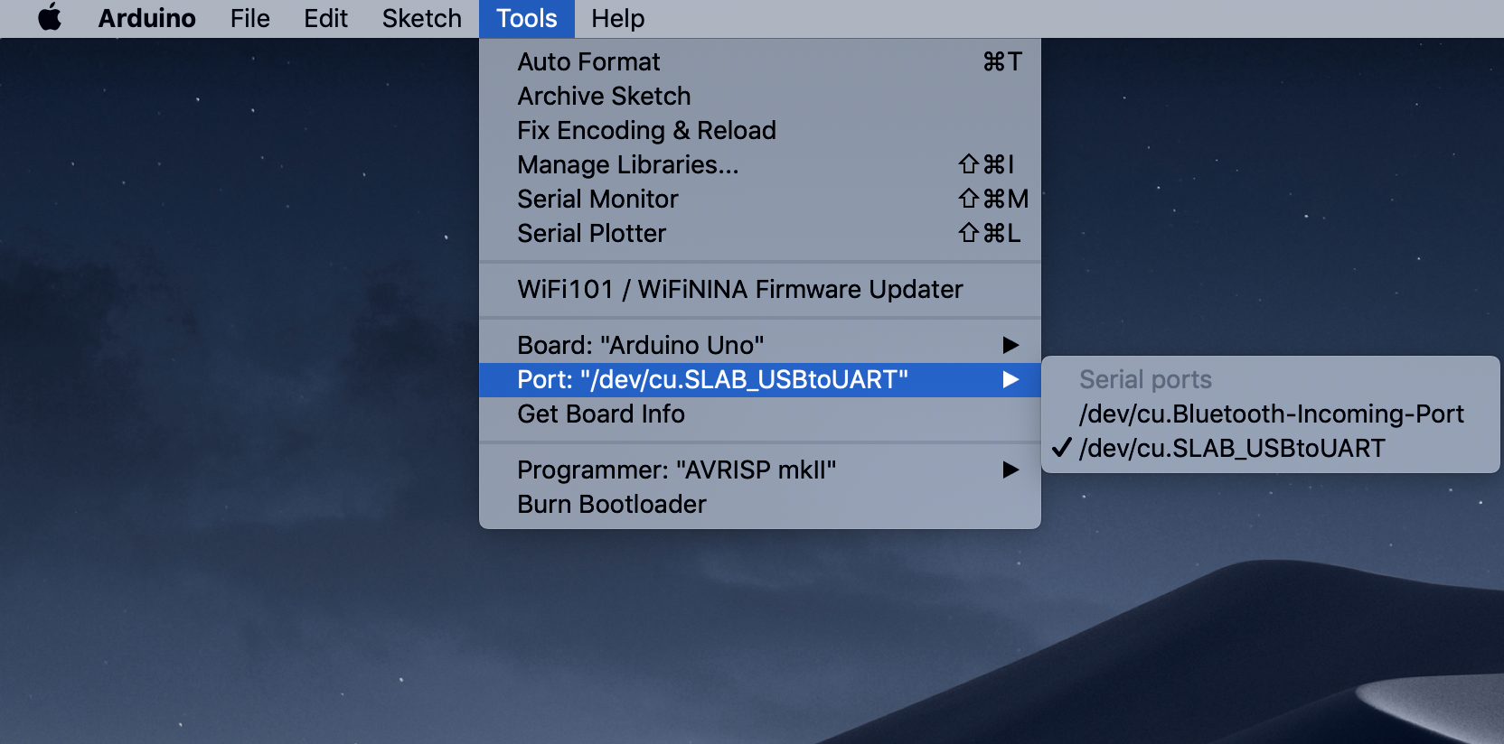
  • Specify the Arduino Hardware Version as an Arduino Uno and the USB Port.
  • Italian Trulli
    Italian Trulli

Read the signal from the Infrared Detector and write Serial

There are two built in functions, setup() which runs once at the beginning and loop() which runs repeatedly.
  • Have the Metro Mini start the Serial Port in the setup function by adding the line Serial.begin(9600);
  • Read from the analog input pin in the loop by assigning analogRead(A0) to a variable.
  • Print the value to the serial port using Serial.println(...)
  • Upload code to the Metro Mini using command-U or ctrl-U.
  • Open the serial port monitor using shift-command-M or shift-ctrl-M.
  • Save your code!

Hint: Make sure your IR Emitter and Detector are facing each other (there is a bump on the front).

Submit a video of your code working to Google Classroom

For today's participation assignment, take a short video (less than 1 minute) of your code working and submit it to Google Classroom.

Part 4: Programming an Infrared Switch

Program an Infrared Switch (Optional)

Write a program that changes the built-in LED state (toggle on/off) when the path between the Infrared Emitter and Infrared Detector is blocked. When the path is no longer blocked the LED does not change.

The Arduino IDE has example code on how to turn on and off the built-in LED. You can find it in File > Examples > 01.Basics > Blink