Heart Rate Monitor |
Goal
- Create a heart rate monitor using the IR Emitter and Detector circuit (from Lab 1).
- Implement Digital Signal Processing techniques.
|
Setup |
Setup
Start with your code from Lab 1 that reads from analog pin A0 and writes to the serial port at baud rate 9600.
Save it as a new Arduino project titled colbyUsername_P01 (with your colby username, mine would be hewolfe_P01).
MyFilter Library
You will need to write a MyFilter Library, with a MovingAverage and a FilterOnePole struct.
I am providing a header file if you would like to use it: MyFilter.h
- Create a header file and cpp file, and save them in the same directory as your Arduino Sketch.
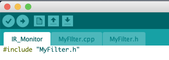
- Include the header file in both your .ino file and .cpp file.
General steps inside the loop
- Read the signal from A0.
- Amplify your signal (multiply it by 100).
- Filter your amplified signal with a lowpass filter, and a highpass filter.
- Use a moving average to smooth the filtered signal.
- Calculate the zero crossing rate to find the heart rate.
- Print the heart rate and the filtered signal to the Serial Port.
|
Moving Average |
Moving Average
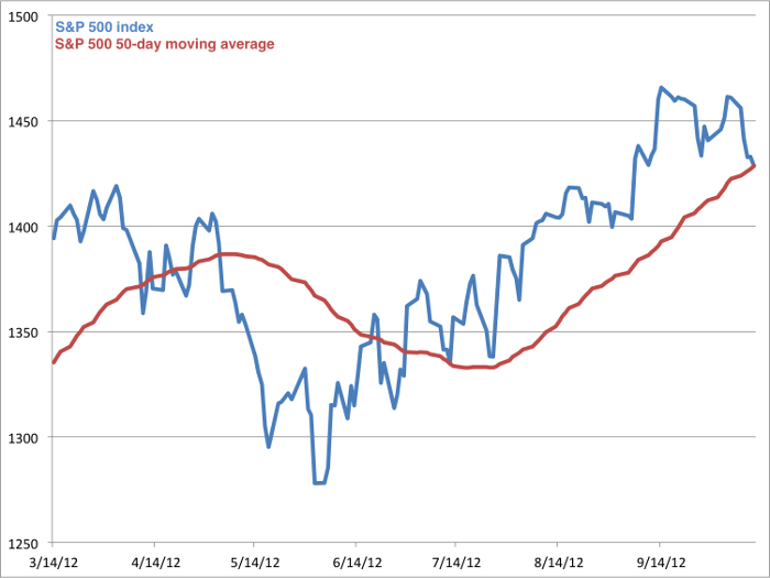
- To smooth a signal implement and use a simple moving average.
- A simple moving average returns the average of the last n elements.
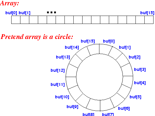
- One way to implement it is to use a circular array. Each time a new value is added it replaces the oldest value in the array.
- To keep track of the current sum of the array, subtract the old value being removed from the sum and add the new value that is being added.
- In the global scope of your program define the array and instance of the struct.
Other ways to implement a moving average are discussed in Chapter 14 Moving Average Filters of The Scientist and Engineer's Guide to Digital Signal Processing.
|
Single Pole Recursive Filter (IIR) |
Single Pole Recursive Filter (IIR)
Highpass and lowpass filters can be used to cancel out noise and light from other sources.
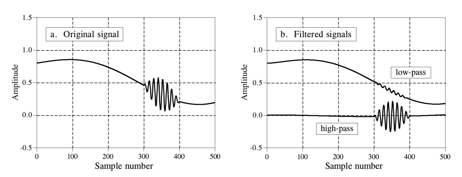 A great introduction to digital filters is available here: Introduction to Digital Filters, and page 7 onward talks about Recursive Filters (IIR).
The algorithm below references Chapter 19 Recursive Filters of The Scientist and Engineer's Guide to Digital Signal Processing.
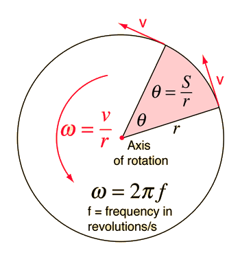
- First, you have to convert the cut off frequency to the filter's time constant in micro-seconds. The filter's time constant τ (in seconds) is 1/ ω, or 1/AngularVelocity.
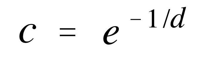
- Our sample length is constantly changing so we need to divide our time constant τ, by the length of our current sample which is the tausSamples (d).
- c, our ampfactor (which is used in deriving a0, a1, etc) is
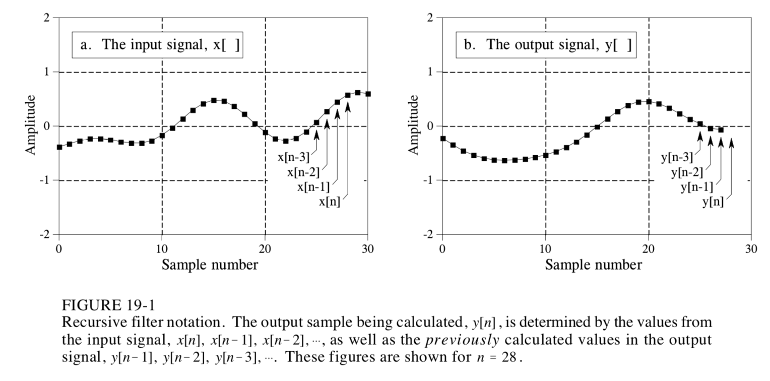
- The general form of Y, our output signal, is

- Lowpass and highpass filters are first order filters so they only include y[n] = a0x[n] + a1x[n-1] + b1y[n-1]
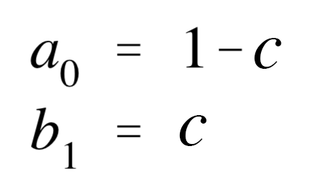
- For a lowpass filter, our constants are
- For a highpass filter, our constants are
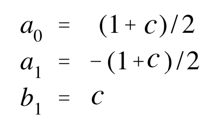
In the global scope, define the high pass and low pass filter instances.
Then update the input value to get the filtered output value in the loop.
(1 beat per minute (bpm) is equal to 0.01666667 Hertz, a normal resting heart rate is between 60-100 bpm. Start with a 1Hz lowpass filter and 2.5Hz highpass filter.)
|
Zero Crossing Rate |
Zero Crossing Rate
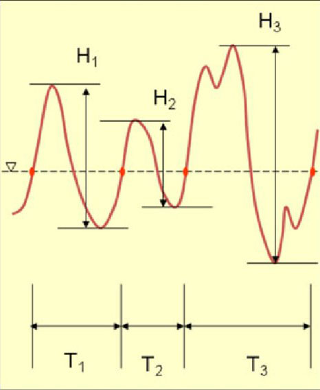
- A zero crossing is when a line intersects with 0.
- The zero crossing rate is the number of times a line intersects zero during a specific period of time.
- By tracking when the sign of the line changes we can calculate the zero crossing rate.
- Calculating the zero crossing along the average value can make the result more accurate.
- Another option is to calculate the zero crossing period. (Represented as T in the diagram to the left.)
In the global scope define variables to keep track of information between loop calls, like the last (filtered and smoothed) signal value, or create your own struct to keep track of the required information.
|
Submission |
Submit your code on Filer
Submit your arduino code in a folder titled colbyUsername_P01 (with your colby username, mine would be hewolfe_P01).
Submit your report and video on Google Classroom
Upload a 1-3 min Documentation Video. Show that your sensor works and the serial plotter is plotting the heart rate and filtered signal.
Attach a Google Doc Report which includes:
- Photo of circuit. Clear photo of the circuit in which the wiring is clearly visible.
- Implementation Section
- What algorithms did you use? How did you implement them?
- Results & Reflection Section
- Try a range of constants for the lowpass filter's frequency cutoff, high pass filter's frequency cutoff, and moving average's window size. How does it effect the signal?
- Do your results make sense?
- What constants did you decide to use for your final heart rate monitor? Why?
- Take your pulse by hand, and then take it using your heart rate monitor. How accurate is it?
- How well does your implementation work?
Acknowledgements Section
- What resources did you use. Include websites, books and anyone you received help from or discussed the project with.
|