Lab 5b: Low Pass Filter Analysis |
Goals
- Design a circuit based on component specifications.
- Wire components based on self-drafted circuit design.
- Create a lowpass filter with a resistor and capacitor.
- Analyze the lowpass filter's effect on amplitude.
|
Part 1a: Design Low Pass Filter Circuit |
Design Your Circuit
Draw a circuit diagram representing your low pass filter wired to the microcontroller.
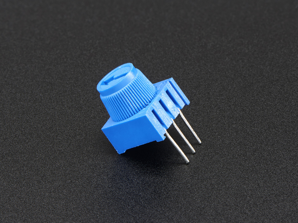
Potentiometer
- Connect pin 1 microcontroller's 5V supply.
- Connect pin 3 to the microcontroller's ground.
- Connect pin 2 to an analog input pin.
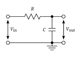
Low Pass Filter
- Connect one end of the 2.2k resistor to pin 2.
- Connect the other end of the resistor to the .1μF capacitor and an analog input pin with a jumper wire (different pin than the potentiometer).
- Connect the other end of the .1μF capacitor to ground (same ground pin as potentiometer).
|
Part 1b: Potentiometer |
Wire the Potentiometer
Wire your potentiometer to your circuit based on your circuit diagram.
Test the Potentiometer
Print the potentiometer values to Serial to make sure it's working.
|
Part 1c: Low Pass Filter |
Wire the Low Pass Filter
- Wire your Low Pass Filter to your circuit based on your circuit diagram.
- Have Hannen Wolfe review the circuit before connecting the micro-controller to power.
Program the circuit
- Set the Baudrate of Serial communication to 115200 in setup
- In the loop use the Tone library to generate a square wave to pin 2.
- Use the potentiometer to set the frequency of the tone to a value between 900Hz and 2948Hz.
- Read from the analog pin connected to the low pass filter and print it to Serial
Analyze the effect of frequency on the signal the low pass filter produces.
- Plot your results using the Serial Plotter and take screenshots of the signal produced at different frequencies.
- Connect the analog in pin directly to pin 2 instead of between the capacitor and resistor. Plot your results using the Serial Plotter and take screenshots of the signal produced at different frequencies.
- In your lab report, include the screenshots. Explain how the generated signal changes when using a low pass filter and at different frequencies.
|
Part 2a: Incorporate the Speaker |
Update Your Circuit
Update your circuit diagram adding the speaker to your low pass filter and the microcontroller.
- Remove the connection between the analog input pin and the lowpass filter.
- Connect the anode (red) of the speaker to the lowpass filter between the resistor and the capacitor.
- Connect the cathode (black) of the speaker to ground (same ground as lowpass filter).
Wire the Speaker
Wire your speaker to your circuit based on your circuit diagram.
|
Part 2b: Analysis |
Analysis
- Modify your microphone microcontroller program to print the peakToPeak.
- Modify your lowpass filter program to do a "frequency sweep", playing tones from the frequency 900Hz to 3100Hz at a step of 200Hz for 5 second each. (eg 900, 1100, ..., 2900, 3100.)
- Record the Serial Monitor results.
- Rewire the speaker to be wired directly into pin 2 and ground.
- Re-run your frequency sweep and record the Serial Monitor results.
- Using the program of your choice, create a graph of the peakToPeak vs Frequency, for both frequency sweeps.
- What conclusions can you draw from these results?
|
Check-in |
Check-in
The goal is for you to have the lowpass filter working by the check-in. You can only turn in extensions if your check-in is ontime and complete.
Submit a check-in document on Google Classroom
Attach a Google Doc Check-in which includes:
- Documentation of the circuit:
- Drawing of the circuit you designed.
- Clear photo of the circuit in which the wiring is clearly visible, wired correctly.
- Analysis Paragraph:
- Include the screen shots from 1c.
- Discuss the results of 1c.
- Include the plots from 2b.
- Discuss the results of 2b.
|