CS 353 Jan 2025     Syllabus       Labs/Projects

Lab Goals Part 1: Buttons Part 2: Calculations Part 3: Speaker Check-in Start Project

Lab 3: Parallel Piano

Goals

  • Wire 7 buttons with different resistors in parallel into 1 analog input.
  • Use a voltage divider to differentiate between different button presses.
  • Calculate the Vout that will be produced for each button.
  • Differentiate between button presses and play a different tone with each button.

Part 1: Buttons in Parallel

Button in Parallel

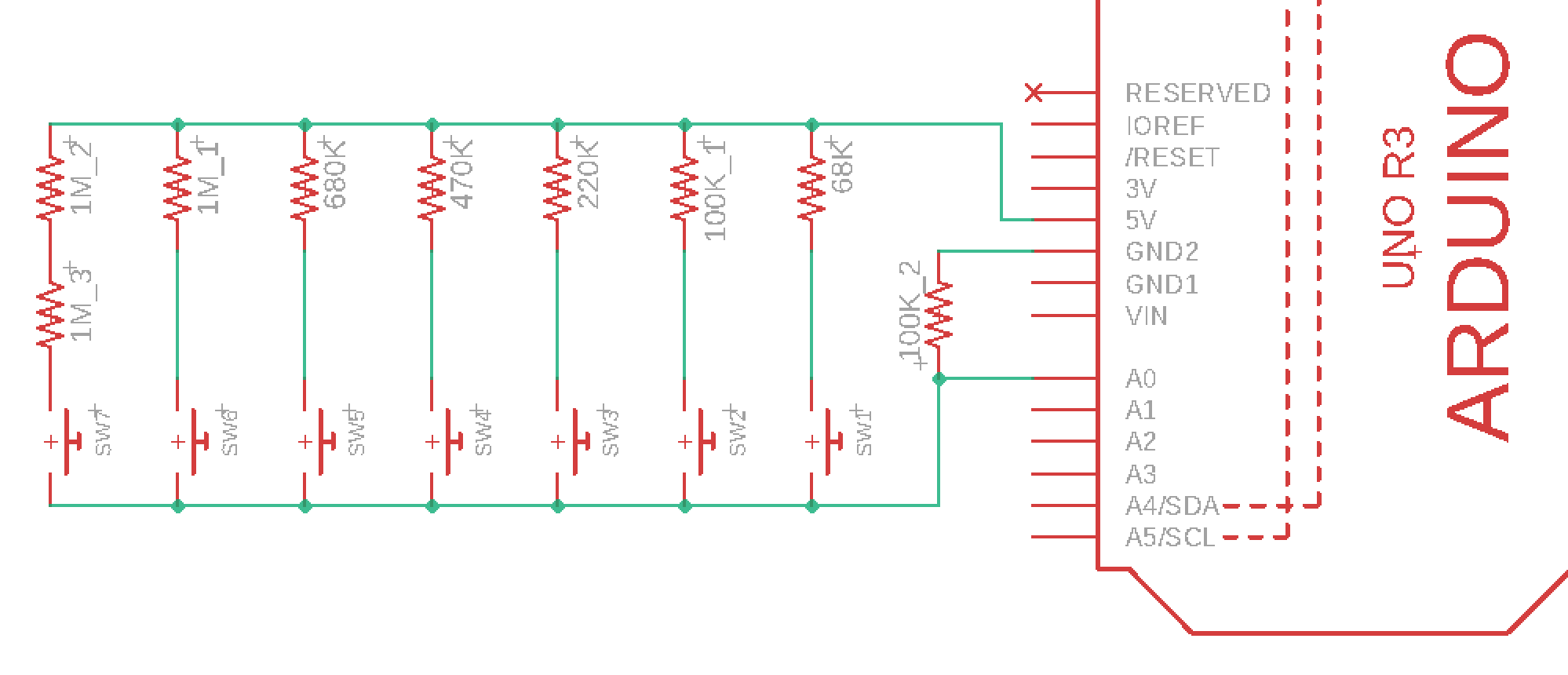
This circuit is designed to produce a different voltage for each button because each button is in series with a different resistor.

Build the circuit

  • Follow the circuit diagram provided.
  • Hint: The power rails (2 vertical columns) do not need to be used for power & ground.

Program the Arduino

  1. Program your Arduino to read from A0 and print the signal to Serial.
  2. Press different buttons. You should see a different value for each button.


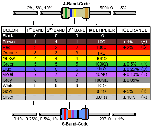
keyboard_circuit.png resistor-color-chart.png

Part 2: Calculations

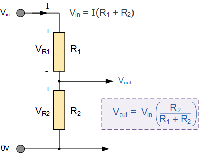
Voltage Divider

resistor-res10.gif
A voltage divider is a passive circuit which produces a Vout which is a fraction of the Vin. In this lab we will be using a voltage divider to differentiate between different button presses.

Calculate expected values

  • For each button's resistor, calculate the Vout.
  • Do your calculated values align with your analog read values?
  • For more information about conversion see the documentation on analogRead()

Program the Arduino

Program the arduino to print the specific resistor value associated with a button when it is pressed.

Resistors in Parallel

  • Draw what the circuit would look like if two buttons pressed.
  • Determine the equation to describe Vout if two buttons were pressed.
  • Use this chapter for more information about resistors in parallel.
    Resistors in Series and Parallel Chapter
  • Include this in your check-in.

Part 3: Speaker

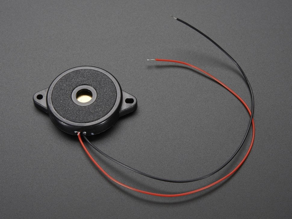
Piezo Electric Buzzer

piezo
Piezo elements convert vibration to voltage or voltage to vibration. They can be used as a buzzer for making beeps, tones and alerts and can be used it as a sensor, to detect fast movements like knocks. It's rated for up to 12Vpp use but you can also use 5V square waves.

Build the circuit

Follow the circuit diagram provided.

Program the Arduino

Use the tone() function to produce a different note frequency (A-G) for each button. Turn off the tone when no buttons are being pressed with noTone(). Here is a reference that includes constants for each note.
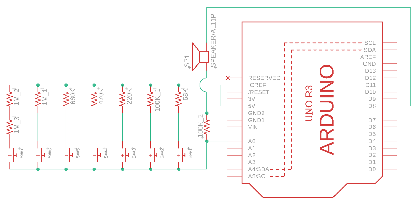

keyboard_circuit_2.

Check-in

Check-in

The goal is for you to have the keyboard working by the check-in. It's okay if you don't, just submit a check-in (video&doc) of what you have done so far and you'll receive 75% on the check-in (-5% of your project grade). You can only turn in extensions if your check-in is ontime and complete.

Submit a video and Check-in document on Google Classroom

Upload a 0.5-2 minute Documentation Video with narration.
  • Show that while you are pressing a button the associated note plays.
  • Show that when you stop pressing a button the note stops.
  • Describe what is happening.
Attach a Google Doc Check-in which includes:
  • Photo of circuit:
    • Clear photo of the circuit in which the wiring is clearly visible, wired correctly.
  • Video Description Paragraph:
    • 2-5 sentences describing what is happening in the video.
      • If complete: How does it work?
      • If incomplete: What is the current issue? Where are you stuck?
  • Vout Calculations Discussion:
    • How did the values you calculated for Vout align with the values you read from A0?
    • Derivation an equation for Vout when two buttons are pressed at the same time.
  • Project Idea:
    • 2-5 sentences describing an idea for a project that incorporates the piezo element (as an input or output device) with the IR sensor and/or the vibrating motor. (Button, potentiometer, and red LED are optional).
      • What is it?
      • What materials would you need?
      • How would you implement it?

Start Project

Registers, Interrupts and PWM

For this project's reading watch these three videos on Registers, External Interrupts and Timer Interrupts.

Introduction to Registers
Introduction to External Interrupts
Introduction to Timer Interrupts
Helpful Reference: ATmega328P Datasheet